An interesting project computer-aided olmasıda a very good feature. Supervision can be said that the RGB PWM circuit PIC16F628 dali assembly prepared with software installed on the RGB data while sending the program’s visual basic code through a source-based communication used in section MAX232 RS232 serial port data is sent from the pic PIC16F628
We are going to control RGB LED with a microcontroller. Using Pulse Width Modulation (English: Pulse Width Modulation or PWM), we can digitally analog signal opwekken.Ik have used a software PWM. This is thus applicable to PIC’s with and without hardware PWM. The LEDs are connected directly to the pic outputs without ballast resistors. This is possible because the outputs are limited to a maximum of 25mA internally.
a MAX232. For a first test, this is not necessary and can be omitted initially. If one wants the colors without herprogrammerren reprogram the microcontroller then the RS232 interface is required If we connect an LED to a square wave with a 100Hz PWM of 50%, the LED will be 50% of the time and 50% off. This can people not see with the naked eye. It’s just too fast. By now setting the PWM 0n 25% LED, 25% of the time and 75%. We only see that the LED is lit. Less bright With this technique we can led to full (PWM = 100%) to completely (PWM = 0%) control.


Visual Basic RGB LED Driver interface

Program LED color according to the codes sent over the timing of the transition period is determined transition format for burning different codes given 23 units also conducted and PWM color variants statements of the Company for the description of shared
Controlling RGB LED using a PIC 16F628. Purpose of the project: An RGB LED multi color burn. Back to the beginning. What is an RGB LED. This is basically not one but three separate LEDs LED 1 enclosure. The 3 separate LEDs have the same 3 colors as a pixel of a TV. Hence the name R ed G reen-B lukewarm. The LED that I use has 1 – connection (say RGB) a 3 + connections (say + R, and + G + B).
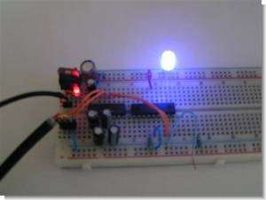
PIC16F628 PWM RGB LED Driver Test
PWM. If we connect an LED to a 100Hz square wave with 50% PWM, the LED will be on 50% of the time and off 50% of the time. We humans cannot see this with the naked eye. Too fast. Now by setting PWM 0p to 25%, the LED will be on 25% of the time and off 75% of the time. We only see that the LED starts to glow less brightly. With this technique we can control the LED from fully on (PWM = 100%) to completely off (PWM = 0%).
Description of generating analog signals with PWM.
Assume that the current through the LED at PWM = 100% is 20 mA.
Then the average current is 10mA at PWM 50%. And 5% 1mA in PWM.
Note: This is the average value. The actual flowing current remains 20mA when the LED is on.
The software uses a playlist in the PIC’s EEPROM. This playlist specifies which function to perform.
functions:
* 01 Random Color Control Long (0.1 to 25.5 seconds)
* 02 Random Color Driver short (0.005 – 1.275 seconds)
* 03 Color Transition (fade) slow (0.6 to 153 seconds) 32 steps
* 04 Color Transition (fade) fast (0.08 to 20.4 seconds) 16 steps
* 05 Random Color Blink (0.1 to 25.5 seconds)
* 06 Set flash rate (0.01 to 2.55 seconds On / Off)
* 00 Return to top of playlist
Single color control: In the software, I chose a byte-per-color PWM control. The color at which the LED should light can be specified in an RGB value.
This results in a probability of 256x256x256 = 16777216 colors.
source: members.upc.nl Computer-Controlled Programmable RGB LED Driver PIC16F628 PWM schematic source code files alternative link
Password: 320volt.com
Published: 2009/07/19 Tags: led projects, microchip projects, microcontroller projects, pic16f628 projects, pwm circuits
Simple Transistor Circuits Free Ebook
Talking Electronics Site new shared a circuit archive actually to be sold “200 Transistor Circuits” book of the circuits for free on the internet in ebook as a shared short descriptions (in English) available, of course, sold Wrox detailed explanations are
Electronic circuits heavily transistor integrated circuits with a few classic’s most easy cost-effective in those circuits
Also integrated transistor connection information corresponding statements about the resistance value of simple explanations connectivity photos