Circuit second part consists of water released into the rf-makers and the information will appear RF-receiver circuit two circuit pic 16f84 micro-controller based on the pic “Reed Relay” use and relay operation rf to convey a sample project also modules source MPLAB files (asm, hex, etc.).’s top to bottom in pdf format PCB, circuit diagrams have a list of materials
4 red LEDs and buzzer on the RF receiver circuit with the signal status can be monitored. Author of the circuit to detect fish under the water for balIkcIsI mention that 🙂 transmitter circuit must be watertight boxed says.
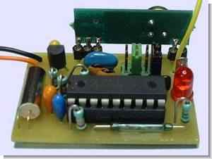
Fish Detector Circuit

Fishing for how effective it can be useful I do not know, but the source code and presence of a hardware reed relays, RF modules use a good example also comes to my mind this circuit burglar alarm circuit as was the development picprograml with people interested in different ideas can give.
This is a set which allows the detection of transmission of the key information with HF to a receiver. Manufacturing is not within reach of a beginner. There is much work to achieve the electronic part that the mechanical part (inclusion in enclosures) The transmitter is designed to be embedded in a waterproof case and attached to a stick wedged in fishing action which it will detect the vibration sensor using a pen. Upon detection, there is transmission of an identification code to a receiver. A receiver can handle 4 sticks. At a reception, if the code is identified, a buzzer sounds and LED lights. The LED remains lit until the fisherman does not give the order of extinction. System design that 4 receivers, so a total of 16 sticks, can operate in the same environment.
source: pagesperso-orange.fr/Doumai Fish Detector schematic source code files alternative :
Password: 320volt.com
Published: 2009/10/07 Tags: microchip projects, microcontroller projects, pic16f84 projects
PIC18F452 Graphic LCD Menu CCS C stopwatch Project
GLCD graphic LCD using PIC18F452 microcontroller on the picture menu, primarily to prepare the necessary photos we draw on our computer. I’ve used MS Paint for this process is already very professional does not need a drawing program will ultimately create a black-and-white photos. No writing required on BITMAP2LCD – Basic Edition software to add and we’ll turn the hex code official. Below you can see bitmaps 128X64 prepared using MS Paint.