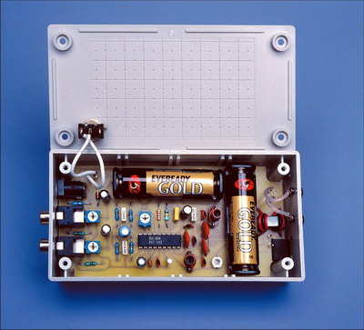
The FM Transmitter circuit built on the BA1404 can work with two 1.5V AA batteries. If desired, a 6 volt dc adapter can be connected. RCA Input sockets have 300-ohm and 75-ohm antenna outputs. You can stream a stereo audio signal from your CD player or other source. The signal can be received via a standard FM receiver.
- Frequency range: 95-105MHz (can be expanded with material changes)
- Transmission range: 40m with folded dipole antenna transmitter
- Current consumption: 10mA
- Distortion: 3% typically at 200mV audio signal level
- Separation between channels: typically 45dB at 1kHz
The FM transmitter circuit is built with a single BA1404 and several passive components, and a small pcb design is made to fit in a small plastic case. It broadcasts in the FM band (88-108MHz), so the audio signal can be received by any standard FM radio or portable radio.
It can use a 300-ohm dipole antenna for improved range in the FM transmitter circuit.
There are many applications for an FM transmitter, especially if it can broadcast in stereo. You can broadcast stereo signals from your CD player or any other source (stereo or mono) to an FM receiver or radio.
The FM transmitter uses a single BA1404 integrated and several other components and fits in a small plastic case. It broadcasts in the FM band (ie 88-108MHz) so that it can be received by any standard FM tuner or portable radio. The FM transmitter is powered by a 3V source and can use a 300W dipole antenna for improved range.
The FM transmitter is powered by 3V instead of the new version 1.5V and you can either come from these two AA cells or run it from a 6V DC plug pack. Operating from two AA cells gives more than double the battery life of a cell because the circuit will continue to operate even when the supply voltage drops below 1V (though power output and range will be greatly reduced).
BA1404 Stereo FM Transmitter Circuit Diagram

Source: http://www.siliconchip.com.au/cms/A_102010/article.html
BA1404 Stereo 3V FM Transmitter Circuit schematic pcb files alternative link:
Password: 320volt.com
Published: 2008/09/04 Tags: analog circuits projects
Quality Headphone Amplifier with TL072 Op Amp
TL072 Headphone Amplifier circuit based on the output of Op Amp and bc328 bc338 transistors simple and low cost circuitry is powered by the supply voltage + – 15 volts symmetrical