Off-Line UPS Uninterruptible power supplies mains voltage rises or falls relay by-pass system thanks to the transformer input primary section level varies USP transformer primary section of various voltage ranges are wrapped 190v, 220v, 250v and so on. In this way, constant voltage output is taken.
Power supply can use for circuit by-pass system is very similar to, you know the regulator’s behind how much voltage if that power is being consumed for example, 0-30V regulated power supply have output voltage of 5 volts when you set back approximately 25v expects the rest of this voltage is spent half your power transistors extreme heats
In addition, this system commercially available in 0-30V regulated power supply though they are being used and transformer output stage 3 .4 trfo do not use multi-standard types will find it easier to have our circuit suitable for two winding transformers
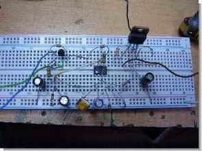
Bypass Circuit Test
Bypass circuit diagram and operation

Circuit LM741 op-amp based on the cube type relay 12v I used the readily available commercially. Where detailed information about the LM741 op amp
Operation of the circuit logic is very simple output voltage by the transformer windings of making the switch, such as 0-30v power supply’s output 12v have set circuit transformer single winding 0 – 15v section of the bridge diode connected to the will of the bridge diode output around 20v will be 20-12 = 8 volts stay behind power transistors will be less heat, less power will spend
LM741 is connected to the leg number 2 instead of 8.2 k potentiometer can use 10 4.8km Set I’ve used in the test circuit output voltage of 14 volts when the relay is active when
Transformer relay connection and operation

Relay operation voltage which is not provided in case common contact with one of the short-circuited transformer single-coil 15V AC diode bridge connects the power supply input to the lower half voltage is applied to the output voltage specified level exceeds the relay other contacts pulls and transformer of two windings 30V AC ends of the bridge is connected to the input full voltage is provided.
Published: 2009/07/26 Tags: analog circuits projects
TDA7294 Active Subwoofer Circuit TL494 Switchmode Power Supply
I’m dealing with a lot of computer power supply circuit arrangement made with EI33 transformer used almost all AT, ATX SMPS control IC TL494 psi resources found in
SMPS output voltage operated 2X30 watt amp 140 volt power circuit TDA7294 made by 2 psi through bridge connections removed mono bass amp transformer windings distributed and repackaged information given in the circuit diagram
🙂 Very interesting design looks complicated, but most of the crowd 220v input filter, DC filter sections constitute a single pcb circuit with a small becomes a regular
TDA7294 Active Subwoofer