Hi, I have done recently attiny2313’l usb application (ATTINY2313 PIC16F88 USB UART converter circuit) then one needs at this time on I did with ATmega8. RS232 portion of the circuit 15 disuse I / O pin with a control board that communicates via usb I designed.
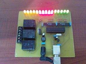
Available in 15 out of 15 relay circuit on a plaque by Cover with too much space. Relay outputs to observe instead I added diodes. We also work with 1,2,3 led to the exit to observe’ve added 3 relays. Circuit fine çalışıyor.atmega8 ‘s usb output due to the hassle of opening and closing process is a bit slow, but speed is sufficient for the control board.
Atmega8 to strengthen the output to the output buffer uln2804’ve added. On the circuit diodes, relays, uln2804 ATmega8 with elements such as external power supply from the USB USERNAME 3.3v regulated with integrated fed. This combination works very well with ATmega8 ATmega8 3.3v 12MHz speed asm code avr309 application note available in the Docs give errors when compiling asm file I found on the internet because I have installed a hex file works fine.
Atmega8 USB Control Circuit Test


USB control circuit schematic pcb code files:
Password: 320volt.com
Published: 2010/04/21 Tags: atmega8 projects, avr project, microcontroller projects
TDA7294 Car Subwoofer Amplifier Circuit TL494 DC to DC Converter SMPS
Car subwoofer amp circuit tda7494 (100W DMOS integrated amp is) based on the bass at the entrance to the opamp’s made with adjustable active filter circuit. Supply circuit TL494 (PWM control IC) made with 12-volt battery voltage of + – 38 volts DC is raising the