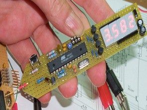
Hello, “Multimeter” was the only title that first came to my mind to. Voltmeter (positive DC voltage) from 0.00 to 9.99 V and 10.0 – 30.0 V with automatic range switching. Frequency counter 0 .. 7.999 MHz (theoretisch. ..) with automatic Change the time base
Logic tester L – Prohibited area – H (actually open line). The hardware is intentionally minimalist, the measurement accuracy miserable, voltage about 2%, frequency about 0.1%. Voltage is applied to unfavorable resistance values , at a frequency slightly ungünsitgen Counter-handling.


Source: mikrocontroller.net/ Atmel Atmega8 AVR Multimeter Circuit schematic AVR Studio source code files alternative link:
Password: 320volt.com
Published: 2008/12/07 Tags: atmega8 projects, avr project, microcontroller projects
PH Meter Circuit Aquarium (led display)
Any aquarium enthusiast knows how important it is to know and control the conditions of the aquarium water for life within it to run smoothly. One of the factors that determine such conditions is the acidity or pH. Unfortunately, pH meters of good quality are hugely expensive. With this in mind I decided to design and build a pH meter, bringing together the precision and reliability with no great cost. The result is the assembly described below, whose main features are: