Frequency in all matters relating to the definition based on frequency is required. In the same way the numeric (digital) Frequency frequency to do the same as the description of the circuit should be implemented.
Frequency: 1 frequency is called the number of periods per second.
Period: a wave of complete rotations made to peryotlu (to speed). Completed the transfer periods are called waves.
Pulse: A pulse is called a half periods. One positive in the first periods, including the other two pulses are negative.
Frequency Unit: HERTZ defined. There are submultiples of value, but there are multiples of the base.
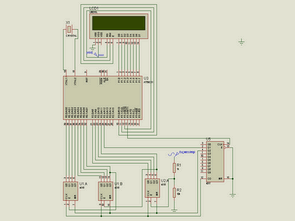
AT89C51 Frequencymeter Schematic

Passing the Periods under Control: After obtaining the reference frequency with each pulse of 1 second, the transition of the periods is controlled with this reference frequency.
Thus, the frequency is made ready to be counted. In other words, the frequency passed for 1 second is delayed for 1 second. Counting is performed during the transition of the frequency, transferred to the indicators during waiting, and the counters are reset to be ready for counting again.
This is how the setup works. Reference frequency is needed for this mechanism to work. We arrive at the conclusion by comparing this reference frequency with the frequency we are going to measure. An AND gate can be used for this kind of operation. In this circuit, we use the 4518 IC and the clock input is controlled.
Frequency Counting: The frequency to be counted in this circuit is connected to the ENABLE input of 4518. RESET terminals are combined and connected to the reset terminal coming from the reference circuit.
The counting pulse terminal is connected to the CLOCK terminal. The Q3 output of the first IC is connected to the ENABLE end of the next IC. Q1, Q2, Q3, Q4 outputs go to the indicator driver integrated.
AT89C51 LCD display Frequencymeter circuit schematic, proteus isis simulation and keil soruce code files; author: Abdülbaki Şahin

Electronic TIG Welding Project
To indicate that I’d like the system is so complicated 🙂 known such a powerful circuit (200 amps) normal abundance IGBT used circuit diagrams to be mixed normal at the same time the cost of high control system TTL and CMOS integrated with the supplied frequency ayarlanabiliry pedal controls and display indicating all floors of the circuit diagrams and PCB files are Industrial applications can be said about this issue detailed resource to find resources found on the site circuit çalışırmı I have no idea, but for people interested in abundance documents have at least feyza be some sections for different applications can be used, for example frequency counter section or on different floors
200A TIG Welding