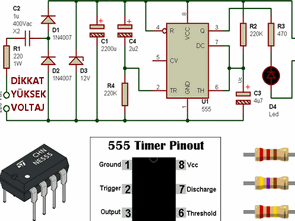
Made with 555 timer integrated timer circuit is supplied from the power supply transformerless transformerless voltage to the circuit drawing too much current is available with leveling . However, where there is a high danger of trying to be very careful with this type of connection is required. R1 , C1, C2, D1, D2 and D3 are the materials which make up the primary feed materials . capacitor study of C1 and C2 D3 12V zener voltage should be 25v and 220v mains voltage will be 1W power resistor R1 lowers the operating voltage must be non-polar capacitor 1uF 400V DC or 275V AC at least should be ..
power supply circuit that determines the effect of the output of several volts is zener D3 . U1 555 timer circuit while the task is to integrate these integrated produced by different companies NE555 , LM555 , etc. . There are varieties are all the same . R4 resistor circuit by varying the duration of the timer can be set or potentiometer can be used instead of this resistor .

Operation of the timer circuit;
Circuit when first energized, capacitor C4 will start to be charged through the resistor R4. Resistors R4, C4 determines the charging time of the capacitor and during this time it would be in the 1 position of the Q output of U1 integrated RL1’s ignition is turned on. C4 capacitor will be fully charged after a while and when it reaches 12V to 0V output Q of U1 will be integrated. Thus relay RL1 and D4 LED will turn off the ignition will take on the position.
Published: 2012/06/10 Tags: 555 timer circuits, analog circuits projects, simple circuit projects
PIC Microcontroller Simulator Program
Isis proteus microcontroller based projects generally used, but only for certain controllers simulator programs more reliable .. I shared the PIC Simulator Program is free and quite an advanced program have the option of six simulators. A 16F628, 18F452, 16F877, 18F452 can use to simulate.
Example sdcc, mikroC pro, hi-tech, c18 code, as well as six card circuit diagram in pdf format in the program’s installation directory ..