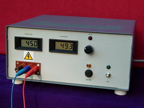
High Voltage Laboratory Power Supply. The power supply we offer provides an adjustable voltage from 50 to 450 Volts at a current of 500 milliamps with 0.1% resolution. Residual ripple and noise value at 100Hz: <1 mV pp over the entire range. Internal resistance is < 0.5 Ω static and < 1 Ω dynamic from 10Hz to 100KHz.
Warning: Execution of this project requires experience and professionalism. All transferred voltages are just as dangerous as those produced in tube amplifiers. So be careful! This project was redesigned in June 2012 in terms of circuits and maps. The circuits presented here are of the new version. This new version is directly compatible with the original version, adds an output short circuit protection circuit and pre-regulation ballast fault detection. BUZ80 ballast transistors are replaced by 2SK1120. 2N5401 transistors are replaced by MPSA92.
Block diagram

450V Laboratory Power Supply

The circuit consists of 3 subassemblies: control, pre-regulation and regulation circuit: Block diagram The control circuit provides +24 Vdc, +5 Vdc and -5 Vdc voltages and allows timed switching of the main 400 VA transformer.
The pre-regulation board provides a stabilized voltage at 485 Vdc at reduced impedance (Z = 5 Ω). The regulation board provides regulated variable voltage from 50 to 450 Volts under a maximum current of 500 mA.
The control circuit allows “soft” powering and provides a variety of power sources. When powered, only two small transformers on the board are active. For 3 seconds, the 400 VA transformer is powered by a 330 Ω 100 Watt resistor that allows the capacitors to be charged while protecting the rectifier bridge, fuses and SIPMOS from deadly overcurrents.
The delay is derived from the delayed load of C1 applied to pin 3 of 741 (IC1) and sets the output to 0V for 3 seconds. When the voltage of C1 exceeds that available on pin 2, the output of the 741 switches to 24 Vdc, causing the REL1 static relay to turn off. The device is then operational.
Two components are added to the circuit to prevent excessive currents in case of power failure: diode D1, which immediately discharges C1 in case of power failure, and 100 Ω resistor R2, which has the same effect in case of power failure, deactivation of the device with the switch (SW1). The power switch is 3 circuit (3RT) “ON-ON” type. Therefore, re-arming immediately after disarming via switch will apply a new time delay of 3 seconds.
The +24 Vdc and – 5 Vdc voltages are the ones that will condition the stability of the assembly, as we will see by examining the regulation circuitry. The implementation of the 78xx and 79xx controllers requires some precautions.
If the layout of the tracks is well studied, the residual output noise can be reduced to below 100 µV. So on the board, the two pins of the buffer capacitors (C3 and C2 for the 7824) must necessarily be between the rectifier bridge and those of the regulator, the ground plane being at the level of the reference pin of the regulator.
Source: novotone.be High Voltage Laboratory Power Supply schematic pcb files alternative link:
Password: 320volt.com
Published: 2008/10/27 Tags: power electronic projects, power supply circuit, power supply project
White Led Lighting for Camera
Prepared for a professional camera fits many models with LED Lighting also has samples of pictures taken with working with 12-volt control circuit with integrated HEF4538BP
The shooting quarters requires proper lighting equipment to remove the shadow of the objective and allow the closure of the diaphragm of optics, to win in depth of field.
Various processes are possible, such as adding flash side that increase the package and make it desirable using a stick handle or support to ensure the stability of the device.