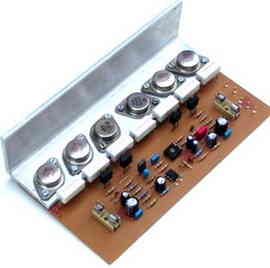
The sound quality is very good, and the high-power amplifier circuit is classic, stable design output transistors TO3 sheath output power is between 200W-500W. With the number of transistors, transformer and a few other component changes, it can provide up to 500W of power. The explanations below belong to the person who designed the circuit.
Output power: 200-500w
Harmonic distortions: 0.01%
Bandwidth: 5Hz-50kHz
Signal to noise ratio: 110dB
Damping factor: 200
Input sensitivity: 1v
Input resistance: 33k
Speaker resistance: 4-ohm
The power amplifier circuit is a high-class, completely universal application, from instrumental amplifiers to professional public address systems to HI-FI devices. The universality of this amplifier is due to its construction, which is known and built worldwide in various variants and with minimal changes to the electrical scheme.
Years of practice and manufacture of this amplifier in many replicas attests to the very high build quality and performance of this amplifier. For speaker impedances from 2-ohm to 8-ohm, it is possible to get 100 to 800W of power with appropriate changes in the values of some components.
UPDATE: https://320volt.com/en/200w-500w-amplifier-powerful-bass-clear-sound/
200W-500W Amp Circuit Diagram

The input sensitivity of the amplifier is 1V and is determined by the resistor R3. By increasing the value of resistor R3, the input sensitivity can be reduced and vice versa… The minimum value of resistor R3 is 330 Ω.
Connect the amplifier to the power supply with resistors between 100-ohm 2w..5w and measure the voltage drop across the resistors, which should not exceed 3V, otherwise there will be an error in the amplifier, such as poor soldering, assembly of defective elements, incorrectly returned semiconductor or the like. has.
After finding and fixing faults, repeat the procedure and measure the voltage drops across the resistors. The voltage at the output should be 0v to connect the speakers. Next, we check the supply voltages at pins 4 and 7 of TL071 (-15v and +15v). There should be a voltage of about -3.5V on pin 6. The voltage drop across R16 and R18 should be about 0.6v. Turn the trimmer TP1 all the way to the left.
Measure the voltage drops across R21 and R22, they should be less than 0.5v otherwise step down R19 to 820-ohms. Now we connect the output transistors and adjust the quiescent current by turning TP1 to the right, the quiescent current will be between 10-20mA


Amplifier Power Supply
One of the most important components in an amplifier is the power supply part as it is essential for sound quality. The best results are given by a stabilized voltage rectifier, but since the cost of such a power supply is very high, the power supply diagram below will meet the quality sound criteria of this amplifier. The secondary voltage and power of the transformer are given in the attached table, depending on the power of the amplifier.

The filter capacitors of the power supply are very important to the power and sound quality of the amplifier. The table shows the suitable capacitor values, they may be used in larger capacities. For 200w, the bridge diode should be at least 10A.
200W 300W 400W 500W Amplifier Circuit PCB schematic modified info:
Password: 320volt.com
Published: 2008/01/12 Tags: audio amplifier circuits, transistor amplifier
Microcontroller GSM Alarm and Control Circuits
Now quite a popular topic with Cell Phone Control with Microchip pic series for those who want to do these types of projects that could give clues will limp a few projects, including projects located in Atmella in 1
Pcb circuit connected pc with AT90S2313 asm hex file and available software
200W 300W 400W 500W Verstärkerschaltung
Ausgangsleistung 500 Watt Mono Amplifier MJ15003 NPN-Transistoren in der Versorgungsspannung der Schaltung Maxi + verwendet – insgesamt 120 Volt bis 60 Volt mit ein paar Änderungen, die Sie verwenden können, vorsichtig sein, Hälfte-200W-300W-400W
We buy complete power amp kit,
300w
600w
1000w
Gostaria de conhecer.
Greetings, I am very interested in your hybrid amplifier of more than 500w, will you have another pcb, for sot247 for example, what other information should I know to reach those powers, I would like to use it for 50w, but also for 800w