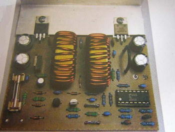
DC DC Converter Circuit Based on TL494 PWM control IC, it reduces the 24v dc input to 12 volts. It has 10 amperes of power. There is a protection circuit with thyristor (BT151) against voltage spikes at the output (crow bar). can be adjusted, but it is generally used as a 24-12 volt converter.
You can test L1 and L2 70uh 10 amps with an EI33 core. Use the C9 2.2nf capacitor in the circuit for 1.5nf or you can use it by rewinding the ring core in the output filter layer of the computer power supplies.
TL494 24V to 12V DC DC Converter Circuit

24v 12v 10A DC DC Converter Circuit diagram

source http://www.bastleni.eu/obsah/menic24.pdf 24V to 12V 10Amp DC DC Converter Circuit TL494 pcb schematic alternative link:
Password: 320volt.com
Published: 2008/04/22 Tags: dc dc converter circuit, power electronic projects, tl494 circuit
Simple DSPIC Experiment Development Board
Beginner level LEDs, buttons, analog input, 24Cxx EEPROM and serial communication with the PC I did try a little experiment where you can make your own set. Wishing to be helpful. Simple DSPIC Development Board
Try this with a set of tiny LEDs, buttons, analog input, read and write 24Cxx EEPROM, serial communication with the PC experiments. PICKIT2 as programmer, I’m using dsPIC dspıc33fj256gp506 in as.
Password please
Hello,
password for all files: 320volt.com
password please
320volt.com