In fact, this circuit was mentioned in my Switch Mode Power Supply SMPS article, but a sought-after circuit can be overlooked. It caused me to write a separate article for this circuit in the mails for the 12 volt 40 amp smps circuit.
A very powerful smps circuit is built on a 40 amp LM3524, instead of this integrated SG3524 or UC3524 can be used, the same only manufacturers are different, the output voltage of the circuit is 13.8 volts, but you can set the output voltage as standard 12 volts, there is overcurrent limit heat protection, the output power transformer used is a little different special winding
A switched-mode power supply designed to power the amateur station. This power supply produces 13.8V regulated better than 1% at up to 40A continuous load current. It has current limitation, making it suitable for direct connection to a 12V backup battery. If the current limit potentiometer is opened, the power supply can deliver up to 60 A intermittently while maintaining regulation. No minimum load is required. The output ripple is about 20mV and the efficiency is 88%. A cooling fan operates based on the average current drawn, and a tri-color LED will let you know if the voltage is normal, too high or too low.
It produces no detectable RF noise at any frequency higher than the main switching frequency of 50 kHz (controlled with an antenna cable wrapped around the operating power supply, tuned from 30 kHz to 40 MHz with the TS450 scope).
SG3524 SMPS 12V 40A

The half-bridge converter is best controlled by pulse-width modulation. There are several ICs that can be used for exactly this purpose. I chose the 3524, which is very simple to use and easy to find. Any 3524 will do the job. LM3524, etc. it could be.
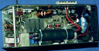
Line voltage enters through a CEE-22 connector with the included fuse and EMI filtering (P1). It is then passed through a 2-pole power switch and an additional common-mode noise filter (C1, L1, C2). Two NTC resistors limit the inrush current. A bridge rectifier transmits power to a large electrolytic capacitor (C3) operating at 300VDC. It consists of the power oscillator, Q1, Q2, components close to them, and the feedback and control transformer (T3). T2 and related components act as primary current sensor.
T1 is the power transformer that delivers approximately 20 V square wave to Schottky rectifiers (D6..9). A toroidal inductor (L2) and six-pack low equivalent series resistance electrolytic capacitors make up the main filter, while L3 and C23..24 are there for additional ripple reduction. 13.8 V is delivered to the output via a series of ferrite beads with some small decoupling capacitors mounted directly on the output terminals.
The control circuit is a 3524 IC (U1) powered by an auxiliary rectifier (D17). The IC includes a voltage reference, oscillator, pulse width modulator, error amplifier, current sensing amplifier, flip-flop, and driving circuit. It senses the output voltage and current level and controls the power oscillator through transistors Q3 and Q4. C37, C35 and R23 are used to implement a full PID (proportional-integral-derivative) response in the control loop.
The quad operational amplifier (U2) is used for two auxiliary purposes: To control the cooling fan according to the average current level and to drive the tri-color LED that indicates the voltage: Green if the voltage is OK, and orange if the voltage is OK. red if it’s too low and too high.
When the unit is powered, the first event that occurs is a current surge that charges C3. This surge is kept at manageable levels by the two NTCs, each about 2.5ohms when cold and then losing most of their resistance as they heat up.
As the operating voltage builds up on C3, R2 and R6 drive the two power transistors Q1 and Q2 to their active regions. They start to deliver a few mA, but only for a very short time, because the positive feedback provided by T3 quickly destabilizes the system. One of the transistors gets an increased base current from T3, while the other sees its base driver decrease. It takes a fraction of a microsecond to saturate one transistor and deactivate the other. Which transistor will start first is unpredictable, but for this analysis let’s assume it’s Q1. Note that since the control circuit is not yet powered, Q3 and Q4 are closed, so D12, D13 and D14 effectively isolate the 26-turn windings of T3, they do not play any role in the result for now.
T1 now sees about 150V on its primary. This produces about +-20V on the secondary. Schottky rectifiers fix this so L2 sees 20 V across it. This inductor will begin to receive an increasing current reflected back to the primary side of T1. The primary current passes through the 1-turn winding of T3, forcing eight times more current to flow into the base of the transistor, which is conductive.
This current causes a voltage drop across R1 and R3, and this voltage is reflected back to T3. After a while the ferrite core of T3 will saturate and this will cause a sharp shock to the base drive of Q1.
will cause it to fall. Q1 will quit transmitting and Q2 will start transmitting. Now the flux in the core of T3 decreases, crosses zero and increases in the other flow direction, until the core is saturated again, turning Q2 off and turning on Q1. Meanwhile, the current in L2 increases and the filter capacitors are charged.
Note that for safe startup, T3 must be fully saturated before T1 gets saturated. If this were not the case, the transistors would have to switch under a very high and potentially destructive current. Keep this in mind if you make changes to my design for any reason.

13.8V 40A SMPS Circuit diagram

http://ludens.cl/Electron/PS40/PS40.html
http://www.n4rpd.org/projects/40A-13.8VPS.htm
http://www.arrl.org/notes/1816/templates/13v40aps.pdf
13.8v 40a smps all files pcb schematic info download:
Password: 320volt.com
Published: 2008/04/23 Tags: power electronic projects, sg3524 circuit, smps circuits, smps projects, smps schematic
24V to 12V 10Amp DC DC Converter Circuit TL494
Circuit TL494 based on the 24 V DC input 12 volts reduces 10 amp has the power output voltage rise against the thyristor protection circuit (crow bar) input voltage 18 .30 volts output voltage 12 .14 volts adjustable, but usually 24 to 12 volts 🙂 converters are used as
TL494 24V to 12V DC DC Converter Circuit