The design of the meter is the result of many experiences in the use and construction of various frequency meters, both factory and amateur. From these experiences, there are several characteristics that a good meter should fulfill. These:
– fastest possible refresh rate (limited only by timebase and prescaler part),
– prescaler input cyclically reset in the measuring cycle to ensure measuring stability (eliminates skip steps at final measuring position),
– stable frequency standard (measurement accuracy depends on it),
– clear display for fast reading (LED) in all (bright) lighting conditions (LCD),
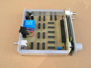
– robust enclosure for desk work,
– universal mains and battery power supply.

The heart of every frequency meter is the frequency standard – without it, you can’t refer to the pulses counted. A common mistake of amateur (not only!) builds is the use of a ten-year (6-8) counter and time base made of quartz with gates and a ceramic capacitor (not NP0). The accuracy of such a standard will at best be about 30 ppm over the entire temperature range, so when measuring the 1GHz frequency the error will be 30 kHz (!!!).
If we use only 3 decades (measurement accuracy 100 kHz) we will not notice the error, but for 6 decades we have to reject half of our result! Therefore, when looking at a frequency meter offer, you should first of all look at the accuracy of the model, not the measuring range (also)! The use of the input prescaler in UHF measurements is irrelevant here, the accuracy of the standard (expressed in ppm – parts per million) is dimensionless – if we use an input divider we have to extend the measurement time by the same amount.
Another problem with the standards is the time to reach the default accuracy and the temperature range of correct operation. On good devices this time is clearly defined. OCXO standards (with heating) need more time (usually min. 15 minutes) and have a larger initial bias – errors exceed 100 ppm (!!!). Also, TCXOs (temperature compensated) show some initial bias. These observations lead to one conclusion – the frequency counter (whatever the standard) min. Leave it on for 15 minutes before measurement and for the entire run time.
The developed device has the following parameters:
– 2 bands (separate inputs) 10kHz – 1.2 GHz measuring range: HF 10kHz – 70MHz; UHF 70MHz – 1.2GHz,
– 4 time bases (measurement resolution 100Hz and 10Hz for HF; 1kHz and 100Hz for UHF),
– sensitivity <30mV @ 50R,
– refresh (measurement stabilization) limited to 4 by the input reset prescaler,
– standard TCXO 10MHz 1ppm (Geyer),
– 7 segment LCD display (much faster operation than alphanumeric LCDs and greater readability than LED),
– metal body,
– power supply DC 10 – 30V or mains 230V AC,
– 10 MHz reference generator output,

The measured signal is supplied via one of the inputs (depending on the measuring range). The HF input has a linearized HC00 gate, which is part of a BFR93A preamplifier + input switching multiplexer operating with a current of about 5mA. The UHF input is connected to the U813A prescaler (divide by 64) and capacitively coupled to the multiplexer (linearized gate) – this allows easy matching of ECL levels to CMOS (prescaler always produces a waveform even if there is no input signal). The input selected in the multiplexer controls the reset prescaler on the HC74 (the HC00 + HC74 duo works fine up to 74 MHz in my version). Then the signal goes to tens 6 times depending on the HC390.
Outputs are controlled by BCD decoders – 7-segment LCD (CD4543) with built-in latches. Decoders must receive the LCD clock signal (anti-phase, off-phase controlled lit segments). The manufacturer of the display gives the optimum value at 32 Hz. The design uses a variable frequency from 4Hz to 30Hz (first use of 600Hz caused a decrease in the contrast of the screen) – the 4Hz frequency looks a bit when viewed from the side (I wonder how long the LCD will last?). An additional inverter and a switch section were used on the T1 transistor to control the point.
The half and base of the frequency counter is the time base. An existing and relatively inexpensive ($11) Geyer TXCO-900 10MHz 1ppm generator was used. The signal from it via capacitive coupling (the signal from it is not rectangular!) goes to the first divider at the 4060, and then to the two dividers HC390 and 4017 (split by 10). The appropriate frequency value is in the 4053 multiplexer controlled by a mechanical switch.
selected from the shelf. The U16 chip is the master counter that generates all the necessary time waveforms (gating, result locking, decades-old reset). The feature of the HC74 chip (acting as a reset prescaler) was used for gating, which consists in not transmitting the signal (gating) at the time of reset (1 time at the RESET input).


Developed the instrument has the following parameters:
– The extent of the measures 10kHz – 1.2 GHz with 2 bands (separate entrance): HF 10kHz – 70MHz, 70MHz UHF – 1.2 GHz
– 4 basis of time (a resolution of 10Hz and 100Hz measurement for HF; 100Hz to 1kHz and UHF),
– Sensitivity <30mV @ 50R,
– Refresh the limited input
– Pattern TCXO 10MHz 1 ppm (made by Geyer)
– LCD 7-segment (a lot more speed than the LCD alphanumeric and greater legibility than LEDs),
– The metal casing,
– DC power 10 – 30V or 230V AC network,
– Output generator standard 10 MHz
Source: sq2ahr.sp-qrp.pl 10KHz – 1.2GHz Frequency Meter with LCD Display pcb sch altwernative link:
Password: 320volt.com
Published: 2008/10/23 Tags: analog circuits projects
2.5v – 27.5v 2Amp Laboratory Power Supply Circuit
Laboratory power supply circuit classical transistor power supplies in a manner similar power transistors, MOSFETS irfp150 Used writer circuit pc power supply box has placed additional olrak volt meter module added circuit toroidal transformer is used the normal steel transformers used in
The primary device is an electronic workshop in the power supply stabilized. After 8 years to use simple 2 Voltage Power Supply (5V and 12V) concluded that the time for change. During the construction guiding principle: “The simpler the better, because the power supply is used for work, and not for the constant repair.
Bonjour
je m’intéresses par le fréquencemètres 10khz a 1,2ghz et je me pose des question sur son réglage
car le lien sur Web.archive.org son mort A pare sure 300volt LINKS-3587.zip et je me trouve rien sur le web.
et si il y a u des mortification .
pourrie vous sils vous plait m’envoyez tout se qu’il me faut pour se projet si possible.
m’envoyez tout les informations et changement si possible
désolé pour la gêne occasionnée
merci
Bonjour,