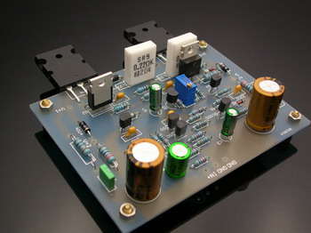
100W Hi Fi Amplifier circuit has quite a stylish design pcb printed circuit mono tracks you want to be found easily, or two-channel stereo is available with two circuits. MJE15030 output power transistors (NPN) MJE15031 (PNP) output filter 16 from the wire coil wrapped around 0.75mm 15ohm 2w on the resistance of the circuit to +35 V-36V DC power supply will be symmetric

There need to do a little adjusting circuit quiescent current to the input and output circuits must be adjusted with VR1 without establishing a connection is made between the speaker output and the chassis will do measurements VR1 is adjusted until indicator shows 50mV.

100W Hifi Amplifier Circuit pcb schematic:
Password: 320volt.com
Published: 2008/01/12 Tags: audio amplifier circuits, transistor amplifier
PICmicro Controlled Dimmer Circuits
PIC16F84, pic16f629, made with PIC12C508 microcontroller series voltj dimmer control applications 220v mains operated and manual controls available in circuits
CAUTION Be careful is working with high voltage capacitor circuit connections Beware + – If you connect the high voltage polarity may be large explosions before running the insured Power Line circuit, protective goggles
Pic with the power control circuits like always in my mind a project that extends from the control of a dimer in applications pic controller integrated supply of 220volt ac mains voltage of the the transformer without the use of a simple non-isolated regulated is being received with you about it if you have problems that I do not think 4 projects are feeds circuits comparisons make the best use
100 W Hifi-Verstärkerschaltung
Die 100-W-Hi-Fi-Verstärkerschaltung verfügt über eine recht elegante Leiterplatten-Monospur, die Sie leicht finden möchten, oder eine zweikanalige Stereoanlage mit zwei Schaltkreisen. MJE15030 Ausgangsleistungstransistoren (NPN) MJE15031 (PNP) Ausgangsfilter 16 von der Drahtspule gewickelt um 0,75 mm 15 Ohm 2 W auf den Widerstand der Schaltung zu +35 V-36 V Gleichstromversorgung wird symmetrisch sein
Es muss ein kleiner Stromkreisruhestrom eingestellt werden, um die Eingangs- und Ausgangsstromkreise mit VR1 einzustellen, ohne dass eine Verbindung zwischen dem Lautsprecherausgang und dem Chassis hergestellt wird. Die Messungen werden mit VR1 durchgeführt, bis die Anzeige 50 mV anzeigt.