Although a bit complicated PCBs in the circuit diagram drawing made easy thanks to an amplifier circuit. Quite elegant in a printed circuit board component layout design very elegant addition to solid volume control located equalizer in the frequency range 15kHz, 50Hz, 250Hz, 1kHz, 4kHz,
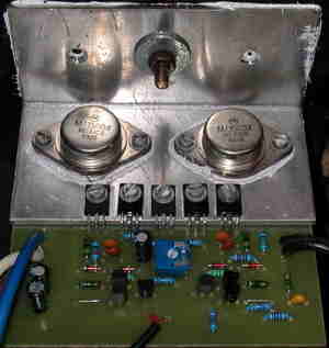
Output power transistors metal-sheathed (to3) transistors forces quite high during installation transistors isolator to isolate Note amp circuit power supply + – symmetric 35 volts DC equalizer circuit the + – 15 volts DC is working with this circuit to run an additional supply can or amp from the power supply can regulate with integrated regulator 7815 7915
100 Watt Amplifier Circuit Diagram and PCB drawings


After making the circuit connecting to the audio output from the speaker without the burden of running the amp draw current from the power source 25 .50 m from R22 1K set with potentiometer
Equalizer Circuit Diagram PCB and Drawings


Published: 2008/01/13 Tags: audio amplifier circuits, transistor amplifier
100 Watt Amplifier Circuit TDA7294 PCB
TDA7294 integrated amp is pretty popular in a very sound system is being used. Has a very clean sound. The materials used in the circuit with very little a few passive components are easy to install.
TDA7294 100V – 100W DMOS AUDIO AMPLIFIER WITH MUTE/ST-BY
100 Watt Hifi Verstärker Schaltung und 5-Band Equalizer
Obwohl ein bisschen komplizierte Leiterplatten in der Schaltplanzeichnung dank einer Verstärkerschaltung leicht gemacht wurden. Sehr elegant in einem Leiterplatten-Komponenten-Layout-Design sehr elegante Ergänzung zu soliden Lautstärkeregelung Equalizer im Frequenzbereich 15kHz, 50Hz, 250Hz, 1kHz, 4kHz,
Ausgangsleistungs-Transistoren Metall-ummantelte (to3) Transistoren Kräfte ziemlich hoch während der Installation Transistoren Isolator zu isolieren Hinweis Amp-Schaltung Stromversorgung + – symmetrische 35 Volt DC-Equalizer-Schaltung die + – 15 Volt DC arbeitet mit dieser Schaltung, um eine zusätzliche Versorgung kann oder laufen Verstärker aus der Stromversorgung kann mit integriertem Regler 7815 7915 regeln
100 Watt Verstärker Schaltplan und Leiterplattenzeichnungen