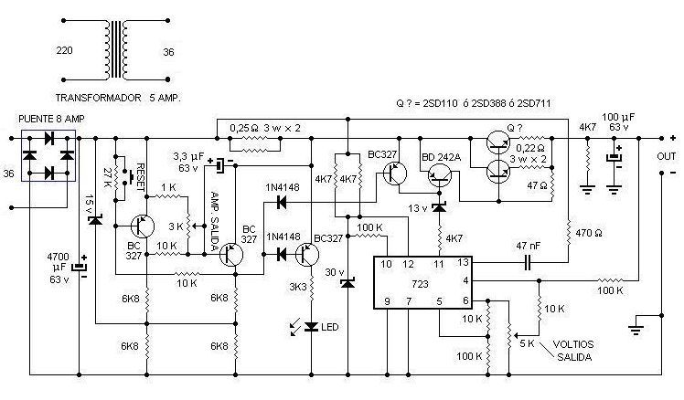
Adjustable power supply voltage regulator Ua723 integrated circuit based on the LM723 can be used in place between 0:50 volts 0.5 amps of current and voltage can be controlled over current and short circuit protection circuitry has long been ar umarımyap opportunity I can find. ‘ll Use the power transformer should be at least 5 amps and 36 volts AC output voltage
Note: 4700 uF capacitors used filter suggestion or 10000uF, 6800uf
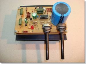
Laboratory Power Supply Circuit 0-5Amp 0-50Volt
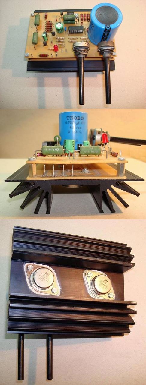
0-50V 0-5V Power Supply Circuit Diagram
Source: forosdeelectronica.com Adjustable power supply circuit schematic pcb files alternative link:
Adjustable 0-5A 0-50V Laboratory Power Supply Circuit LM723 ZIP File Password: 320volt.com
400W DC to DC Converter Power Supply Circuit SG3525 DCDC SMPS
DC to DC converter PWM sg3525 SMPS control circuit transformer model based on integrated EE42/21/15 far as I know there was on the market. 4N35 opto feedback with Kubla made stable driver output MOSFETs IRFZ48 4
You can use it to run the amp 12 volt car battery voltage symmetrical + – raises to the level of 2 × 40 volts 400 watts of power “remote” input can be switched on and off with the car stereo
12V DC to DC 40V Symmetrical
Dear Admin/Viewer;
The Schematic is wrong. why the pin 9 of the chip is grounded ?
Hi,
There is no problem connecting the “nc” pin to the ground.
Dear, I have made the power supply voltage and protection work fine but the current control does not work and I can not get it to work. What is wrong. Kind regards.
Hell I am a irani not spekink englesh
https://ibb.co/bgWCDY6v
Hello, look at the enclosed schematic, great power supply, checked and double-checked everything, but there is a serious error in the current control in the schematic that cannot work, I would like to know what is wrong with the schematic regarding the current control.